Industrial Equipment and Protection Management System
L2Proxy provides a complete management system for industrial equipment definitions, operational points, safety profiles, and equipment-specific protection policies. It is not a fixed catalog: authorized users can create, clone, customize, govern, reuse, and retire industrial content throughout its engineering lifecycle.
Customer outcome: build and govern a reusable industrial asset knowledge base, introduce equipment with consistent point and protection models, and adapt each definition to the site's approved engineering philosophy.
Purpose and expected outcome
This section explains how industrial equipment knowledge is created, cloned, reviewed, changed, and reused. After reading it, the customer should understand how equipment, points, limits, commands, safety profiles, and baseline protections are governed throughout their lifecycle.
This chapter is self-contained for electronic distribution and print. It describes the delivered industrial content, not a demonstration screen or a future roadmap.
Management is the primary capability
The system provides complete lifecycle management for both equipment and their linked protections:
- create a new equipment definition from the ground up;
- clone an existing definition as the controlled starting point for another model, feeder, plant, or site;
- add, edit, or remove monitoring points, command points, engineering limits, normal states, alarm levels, command permissions, and safety prerequisites;
- create and maintain the protections associated with each equipment point;
- search, filter, inspect, and compare managed definitions;
- remove individual or selected records with dependency awareness;
- export reviewed content for controlled transfer, backup, or audit;
- preserve the source definition and version used by each operational asset;
- revise the central library without silently changing deployed equipment.
The delivered equipment definitions are immediately usable starter content inside this management system. Their quantities describe the current predefined library, not a product capacity, licensing limit, or maximum number of customer-defined assets.
One reusable industrial model
Equipment type
      ↓
Monitoring and control points
      ↓
Normal states and operating limits
      ↓
Permitted commands and prerequisites
      ↓
Baseline protection
      ↓
Site-specific engineering approval
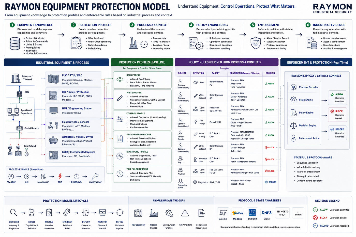
Figure — Equipment protection model: reusable equipment knowledge, protection profiles, and derived policy rules.
The equipment definition contains intrinsic engineering knowledge. Site placement, network identity, and operational bindings are applied when the definition is used for a real asset. This allows one reviewed definition to support several sites without mixing reference engineering with a specific installation.
Predefined starter library
The system is supplied with 13 predefined equipment definitions, 36 operational points, 36 point-level safety profiles, and 66 baseline protections across primary, switching, protection, and generation equipment. Customers can use these definitions directly, clone and adapt them, or create entirely new equipment families.
| Equipment | Points represented | Example baseline protection |
|---|---|---|
| 11 kV busbar | Bus voltage measurement | Permitted band, high/low alarm, out-of-range detection |
| Capacitor bank | Status and switching control | Valid state, approved switching commands, Select-Before-Operate |
| DER intertie breaker | Intertie status and Open/Close control | Approved commands, SBO, voltage and synchronization prerequisites |
| Distributed generator | Active power and export measurements | Permitted measurement range and export thresholds |
| Feeder breaker | Breaker status, Local/Remote mode, Open/Close control | Remote-mode prerequisite, lockout inhibition, approved commands, SBO |
| Feeder protection relay | Trip, lockout, pickup, target, reset/acknowledge control | Alarm states, close inhibition under lockout, approved reset control |
| Fault indicator | Fault indication | Read-only point protection and alarm-state monitoring |
| Load-shedding relay | Shed status and command | Approved commands and controlled operating sequence |
| Recloser | Status, protection indications, control, and operating context | Alarm states, command restrictions, SBO, protection-aware operation |
| Sectionalizer | Status and sectionalizing control | Valid states and approved isolation commands |
| Normally open tie | Tie status and Open/Close control | Normally-open operating intent, approved commands, SBO |
| Power transformer | Loading, winding temperature, tap feedback, tap command | Alarm/critical bands, permitted tap range, single-step command restriction, SBO |
| Voltage regulator | Voltage, tap feedback, raise/lower or setpoint control | Voltage band, permitted tap range, bounded command movement, SBO |
These are reusable starting definitions—not the boundary of the managed library. The customer's protection study, equipment manuals, operating procedures, nameplate limits, and approved switching philosophy remain authoritative for the deployed values.
The complete point-by-point inventory is included in the Base Equipment Catalog. No access to the management console is required to review that inventory.
Point-centered engineering
The most valuable part of an equipment definition is its point catalog. Each point can carry the industrial context needed by operations and protection engineering:
- whether it represents a status, measurement, alarm, feedback, or command;
- the process meaning and engineering unit;
- normal, permitted, alarm, and critical operating values;
- whether it is read-only, controllable, alarm-bearing, or critical;
- approved command actions;
- whether Select-Before-Operate is required;
- required equipment or process prerequisites;
- the recommended response when the protection is violated.
This turns an anonymous point number into a reviewed statement such as “transformer winding temperature,” “breaker remote/local mode,” “relay lockout 86,” or “OLTC tap position command.”
Baseline safety profiles
Every current equipment point has a corresponding safety profile. Four core protection patterns cover common industrial needs:
| Protection pattern | Industrial purpose |
|---|---|
| Permitted state | Detect an invalid binary state and identify alarm or lockout conditions |
| Safe analog range | Monitor normal bands and distinguish alarm, critical, and physically invalid values |
| Permitted switching command | Allow only approved control actions and enforce required control sequencing |
| Permitted setpoint range | Reject values outside the engineering band and limit unsafe command movement |
Profiles can operate as monitoring controls or enforcement controls. This supports a progressive rollout: observe behavior first, confirm site assumptions, and then enable approved blocking where operationally appropriate.
Practical protection examples
Feeder breaker
The baseline definition associates three operational points:
| Point | Meaning | Initial protection |
|---|---|---|
| Breaker status | Open or closed feedback | Only recognized states are accepted for interpretation |
| Remote/Local mode | Whether SCADA control is permitted | Remote mode is required before accepting a remote switching command |
| Breaker control | Open or Close command | Only approved latch commands; SBO required; close inhibited during lockout |
This provides a coherent view of command, mode, and feedback instead of treating each point as an unrelated network field.
33/11 kV transformer
| Point | Meaning | Initial protection |
|---|---|---|
| Loading | Percentage of rated capacity | Alarm at the approved loading threshold; critical escalation above the high limit |
| Winding temperature | Thermal condition | Normal, alarm, critical, and invalid measurement bands |
| Tap feedback | Actual OLTC position | Valid tap-position range and discrete step expectation |
| Tap command | Requested OLTC position | Valid setpoint range, one-step movement preference, feedback relationship, and SBO |
Feeder protection relay
| Point | Meaning | Initial protection |
|---|---|---|
| Trip indication | Protection operated | Alarm on operated state |
| Lockout 86 | Lockout active | Alarm and inhibit associated breaker closing |
| Pickup/Started | Protection element pickup | Immediate operational indication |
| Target operated | Protection target latched | Alarm and investigation evidence |
| Reset/Acknowledge control | Clear or acknowledge protection target | Only approved actions and SBO sequence |
DER intertie breaker
The intertie profile covers status and control while recognizing that closing a DER interconnection is not an ordinary switch operation. The baseline protection requires approved Open/Close commands, Select-Before-Operate, acceptable bus voltage, and a valid synchronization or dead-bus condition before close acceptance.
Operational protection library
The related protection library organizes reusable protections by:
- equipment and point;
- protection purpose;
- monitoring versus enforcement behavior;
- alarm, range, command, setpoint, and sequence control;
- readiness for operational use.
An engineer can search for an equipment type, inspect its points and baseline profiles, review the linked protections, and adapt them to the customer site. The library avoids starting each project from an empty policy while keeping every final decision reviewable.
Managed lifecycle
Both equipment definitions and linked protections have a complete management workflow:
- create a new reusable definition;
- clone a reviewed definition and adapt it without altering the source;
- search and filter by equipment class, type, protection purpose, or readiness;
- inspect complete equipment, point, and protection details;
- update definitions under engineering control;
- remove individual or selected library entries with dependency awareness;
- export a reviewed library for controlled transfer or backup;
- preserve the source definition and version used when an operational asset is created.
An operational asset receives its own snapshot of the selected definition. Later library changes do not silently alter the deployed asset. This supports traceability, controlled change, and repeatable engineering across projects.
Customer workflow
- Select the closest equipment definition.
- Review its monitoring and control points with operations and protection engineering.
- Confirm normal states, units, limits, alarm levels, and criticality.
- Review permitted commands, sequence requirements, and process prerequisites.
- Create the site asset while preserving the selected library version.
- Validate protections against representative traffic and operating scenarios.
- Begin in monitoring mode where required.
- Enable approved enforcement after site acceptance and change control.
Why this matters
- Faster engineering: start from equipment-specific knowledge instead of a blank rule.
- Consistent protection: reuse reviewed point and protection models across similar assets.
- Fewer mapping errors: keep status, command, feedback, units, and intent together.
- Shared industrial language: align operations, protection, control, and OT security.
- Safer rollout: separate reference definitions from site-specific assets and approvals.
- Auditable change: retain the definition and version used for each operational asset.
- Scalable deployment: expand the library without hard-coding one customer's plant.
- Customer ownership: build and govern an extensible customer-specific equipment and protection knowledge base beyond the delivered starter content.
Protection boundary
Baseline profiles are operational and available for deployment, but they are not a substitute for equipment settings, relay coordination, process interlocks, safety instrumented functions, or customer engineering approval. They provide network-level monitoring and enforcement aligned with the observed industrial protocol operation.
Continue through the library
- Base Equipment Catalog: all 13 delivered equipment definitions and all 36 points.
- Point and Safety Profiles: how engineering limits, states, commands, and prerequisites are represented.
- Protection Use Cases: customer-facing operating scenarios and the protection outcome.
- Engineering Lifecycle: creation, review, reuse, versioning, deployment, and change control.